Focal Mechanism
Definition of fault, nodal plane or double couple
A double couple source can be describey by three parameters:
- strike
- dip
- rake
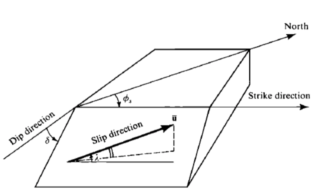
Definition of fault geometry. Figure from P114 of AKi & Richards (1980).
Note that, the coordinate system in Aki & Richards (1980) is NED, North as x direction, East as y direction, Down as z direction.
In NED coordinate system, the fault normal vector can be expressed as:
\[\begin{split}\hat{\mathbf{v}} =
\left(
\begin{array}{c}
{-\sin \delta \sin \phi_s} \\
{+\sin \delta \cos \phi_s} \\
{-\cos \delta}
\end{array}
\right)\end{split}\]
the slip vector can be expressed as:
\[\begin{split}\hat{\mathrm{u}} =
\left(
\begin{array}{c}
{\cos \lambda \cos \phi_s + \sin \lambda \cos \delta \sin \phi_s} \\
{\cos \lambda \sin \phi_s - \sin \lambda \cos \delta \cos \phi_s} \\
{-\sin \lambda \sin \delta}
\end{array}
\right)\end{split}\]
How to obtain the auxiliary plane
The relationship between the fault and auxiliary planes is:
- the fault normal of fault 1 is the slip vector of fault 2
- the slip vector of fault 1 is the fault normal of fault 2
Thus,
\[\begin{split}\left(
\begin{array}{c}
{\cos \lambda_{1} \cos \phi_{s_{1}} + \sin \lambda_{1} \cos \delta_{1} \sin \phi_{s_{1}}} \\
{\cos \lambda_{1} \sin \phi_{s_{1}} - \sin \lambda_{1} \cos \delta_{1} \cos \phi_{s_{1}}} \\
{- \sin \lambda_{1} \sin \delta_{1}}
\end{array}
\right)
=
\left(
\begin{array}{c}
{-\sin \delta_{2} \sin \phi_{s_{2}}} \\
{\sin \delta_{2} \cos \phi_{s_{2}}} \\
{-\cos \delta_{2}}
\end{array}
\right)\end{split}\]